How to Make a Rotor
Warning: Use eye protection at all times, preferably goggles; bits of plastic will be flying everywhere while you dremel holes in your components. Plastic may melt if dremel speeds are too high; stop the tool if this begins to happen and let the plastic cool. Protect all surfaces from spilled glue, dremel bits and drills; we covered our tables with cardboard. Magnets can be very dangerous if you use larger magnets than we recommend: you can pinch your fingers badly if they get close to each other and suddenly snap together while your hand is in the way. Do not let children play with magnets. Magnets are dangerous if swallowed. E6000 glue is also unsafe for consumption, and we recommend good ventilation while the glue is wet.Step 1. You will need to drill holes in eight old compact discs. This will be your stack of platters, which running water will flow across. The flowing water will make them spin, and the holes are for the water to rush through. The water will enter from the side of the CD case and drain out the bottom. Each CD needs three holes, which will be about an inch long and crescent-shaped, and fairly near the center of the discs. Space the holes so that the CD will maintain its structural strength; if the holes are close together the plastic may crack. Use a workbench with a hole in the center, and attach the dremel to it from underneath. Drill a starter hole in each section with a drill bit, and then move the CD over the dremel to cut out the larger shapes with a router bit. Making a jig out of a flat CD case is helpful; you can spin the CD on the center mount, allowing you to create smooth crescent shapes with the dremel. To do this, you will need to drill a hole in the bottom of the CD case in the correct location, which the dremel bit will protrude up through so it can cut into your CD. Try to adjust your speed so that the friction does not simply melt the plastic; if it does, remove melted bits from your tools before continuing to drill or cut.

Image by Oluwa Jackson
Step 2. Next, drill a large hole in the side of the CD case, and six large holes in the bottom of the case to make your water’s inlet and your outflow. The hole at the side should fit the hole you will drill in the plastic ice cream scoop you’ll use to funnel the water into the case. Keep a flap attached to the side of the hole that you can use to mount a screw through it; this will go through the top of the ice cream scoop to hold it securely on the case.

Image by Oluwa Jackson
Step 3. The CDs you’ve made into platters will need spaces between them about as thick as a CD. That’s because the surface area of each CD needs to be exposed to the rushing water; the water will cling to the surface of each CD to make it spin. This is due to adhesive, cohesive, and boundary layer forces, which are properties of water made possible by the polar structure of water molecules. To make spaces between the CDs, we used nylon spacers that we bought at the hardware store. Make sure that the spacers don’t cover up any of the holes you’ve drilled. Rough up the spacers with sandpaper, and use E6000 glue to attach each spacer to each CD, except for the bottom spacer: the bottom CD needs to spin freely upon the spacer attached to the base of the spindle, which should still be smooth. Make sure that the holes you drilled in the CDs line up with each other as you glue the stack. Make sure not to get any glue whatsoever on the upright spindle of the CD case, as the CDs will need to spin rapidly on it.

Image by Oluwa Jackson
Step 4. Next you will need to attach the plastic ice cream scoop to the rotor. You may need to use a belt sander to shape the scoop to fit snugly against the curve of the side of the CD case. Drill a hole in the base of the handle big enough to fit a hose into, and a hole through the curved inside surface of the scoop down into the handle. Fit the scoop against the side of the CD case, and determine where to drill to attach a screw to the flap you left in it. Drill your holes, and counter-sink a brass screw such that the head of the screw will be set into the plastic flap and curved inner surface of the scoop, and the nut will hold it onto the outer surface of the scoop. Once the scoop and case are screwed together, use E6000 glue to seal all holes around the edges where they meet to attach them more securely together and prevent water from leaking out. Let the glue dry overnight.

Image by Oluwa Jackson

Image by Oluwa Jackson
Step 5. Now you have built the piece that will spin. You still need to attach the part that will generate current: magnets. We used six ½ inch x 1/8 inch neodymium rare earth magnets. These will be glued, evenly spaced in a hexagon, to the top CD of your platter. This is the 9th CD, and it doesn’t have holes drilled in it. The magnets must be arranged so that they alternate polarity; for example, if one magnet has the south pole facing up, then the two next to it need to have the north pole facing up. We used E6000 glue to attach our magnets, marking their polarity on the tops with a permanent marker. Magnets with the same pole facing each other repel each other, and magnets with the opposite poles facing each other will be strongly attracted to each other. Test your magnets this way to determine which sides need to be facing upwards. Once you have your magnets attached, glue the top CD to the spacer at the top of your stack, being sure to leave enough room so that the CD case isn’t touching the tops of the magnets; they need to be able to spin.

Image by Oluwa Jackson
Congratulations: you have finished building your rotor! Now for the next step: the stator.
How To Build a Stator
A stator is made by making windings of copper wire, called magnet wire, in a trapezoidal shape. We made six windings of 200 turns each. Your windings must all have the same number of turns. They must fit directly over the magnets without the windings touching each other, so plan your dimensions accordingly. We used nearly a pound of enameled 24 AWG magnet wire. The windings must be wound tight, and held together securely so they don’t unwind; there should be no gaps between the wires. We used tape wrapped around the straight sides of the trapezoids to hold the windings together before we glued them down. Leave about eight inches of wire loose at the beginnings and endings of the windings, because you’re going to need to attach the windings to the rectifier. Use a piece of tape to mark the wire at the beginning of the winding.Step 1. You will need to wind your wire around a form, so determine the size of the trapezoid you need and use pop rivets between two small wooden discs to make the corners. The wooden discs should be held half an inch apart by a small-diameter nylon spacer in the middle of the discs, glued onto only one of the discs. Pop rivets will allow you to attach and remove one of the discs, so you can get your windings off the form once they are wound. A screw and nut threaded through the center of the form will hold the form together while you are winding the wire.

Image by Oluwa Jackson

Image by Oluwa Jackson
Step 3. You will need to glue your windings to a plastic platter. We improvised and used the lid of a food container. It needs to be larger than the diameter of your generator, because it is going to sit on top of it with the windings over the magnets. Like the magnets, the windings need to alternate polarity. So if one of your windings is wound counterclockwise, the two next to it need to be wound clockwise. Just flip the winding over to get the correct spin direction, tracing it from the start of the winding which you marked with tape. Once your windings are evenly spaced over the magnets, and you have made sure they are alternating spin direction, glue them to the plastic platter with E6000 glue. After this dries, apply more glue all over the windings to help keep them wound together, making sure none of your loose wires get glued to the wires from a different winding. The loose wires should all face the outside edge of the platter. You can use superglue for this if you prefer.

Image by Oluwa Jackson
How to Test Your Generator with a Water Pump
To prove that your generator works, you need to make it spin. A freestanding test appropriate for a science fair is a bucket of water with a water pump, which you will attach to your generator. Home use will most likely involve attaching your generator to a faucet while you fill up your sink, pool or bathtub, and it will not require a battery or a pump. To use a water pump to test your generator, you need bucket with two holes in the lid. One hole is for water to pour into from the bottom of the generator; it should be big enough to leave the holes you drilled at the bottom of the CD case exposed, but small enough to hold up the generator. The second a hole is for the water pump to draw water through. Rather using than a lid, you can hold your generator over the bucket with a pair of small planks, but if you do you must be careful not to drop your electronics into the water.
Image by Oluwa Jackson
Step 1. Attach a hose between the outflow of the water pump and the intake of the generator, using a hose clamp. Dip the other end of the water pump into the water in the bucket (at least a gallon), making sure the inlet is not blocked in any way, nor resting with the inlet directly downward on the bucket's bottom.
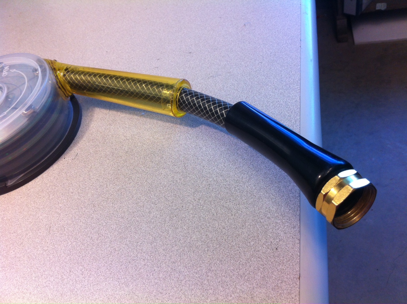
Image by Oluwa Jackson

Image by Oluwa Jackson
Video by Oluwa Jackson, music by The Chemical Brothers
Step 4. Hook your stator wires up to a digital multimeter (DMM) see how much voltage you are generating. To do this, set the DMM to alternating current. Then tie all your positive wire ends together, and all your negative wire ends together, and hook them up to the DMM test leads. Once you determine the voltage your generator is outputting, you can determine the specifications of your capacitor and voltage regulator.
Troubleshooting: What do you do if your test fails and your generator doesn't spin? We have encountered four potential problems:
- Insufficient water force. You can address this by narrowing the turbine's water inlet, forcing the water into a stronger and more concentrated stream. We used putty.
- Water flow is poorly aimed at turbine stack. Experiment with different angles of water flow until you find one that creates a spin.
- Turbine housing is too tight. Make sure nothing stationary touches your magnets. Also, make sure nothing stationary touches the sides of your discs as they spin.
- Too much friction between spindle and turbine. Make sure there is no glue or tacky material rubbing on surfaces that need to move smoothly past one another.
How to Hook Your Generator To a Load
You must now convert the alternating current (AC) you are generating to direct current (DC). To do that, attach your loose stator wires to a bridge rectifier, test it to discover its output, and then choose an appropriate capacitor and voltage regulator as I will discuss below.Step 1. A bridge rectifier has four pins, which you insert through four holes in a breadboard. You will need two bridge rectifiers, placed next to each other. They have a positive and a negative end, so find where these are marked and line them up with each other, with the positive ends on the same side. The next step is to add the red positive and black negative wires leading from the breadboard to the load, so it's time to prepare the positive and negative leads to be soldered. Cut a ten inch length of insulated red wire, and a ten inch length of insulated black wire, and strip 3/4 of an inch of the insulation off the ends. Twist the bare wires, and tin them with solder. This holds the exposed wires together with a conductive material. The red wire will be soldered onto the positive ends of the bridge rectifiers, and the black wire will be soldered to the negative ends; the proper ends are marked in the rectifiers. Note that each wire connects to both bridges; you need to make sure you strip enough length of wire so that it reaches between them. Your stator wires are be soldered between them, only connected to one bridge each. This is how your breadboard will look from the back: note the soldering iron at a center pin, where the magnet wire is being attached.

Image by Oluwa Jackson

Image by Oluwa Jackson
Step 3. Now test your output with either a DMM or oscilloscope. This will help you determine the specification of your smoothing capacitor. A smoothing capacitor reduces fluctuations so that current is steadier; otherwise the waveforms are humped waves and drop to zero periodically, which would interrupt the flow of voltage to your device. The capacitor has two pins that you will push through the breadboard. The positive end of the capacitor attaches to the positive end of the bridge using the red wire, and the black wire attaches to the negative end. This carries the rectified current through the smoothing capacitor, and then to the load, with red and black wires as before. The capacitor pictured below, which is appropriate for our generator's output, is rated at 200 Volts and 470 microfarads.

Image by Steven Jackson
Step 4. Attach your output to a load. The load can be anything that uses electricity at the voltage you are outputting. You can test your output with a lightbulb first to make sure it's safe. A generator like this can charge a rechargeable battery; it could charge a cell phone, or power a small blender. In this video, we attached our generator to an oscilloscope with the red and black wires so we could measure the voltage output it generated. We spun it on a Dremel tool at varying speeds, proving that it was generating current by the waveforms you can see on the oscilloscope, though you can also test your output with a DMM:
Video by Oluwa Jackson, music by Skrillex
You’re all done! Now you can attach your turbine to a faucet to generate electricity whenever you wish to power a small electronic device or charge a battery.
No comments:
Post a Comment